Chillers
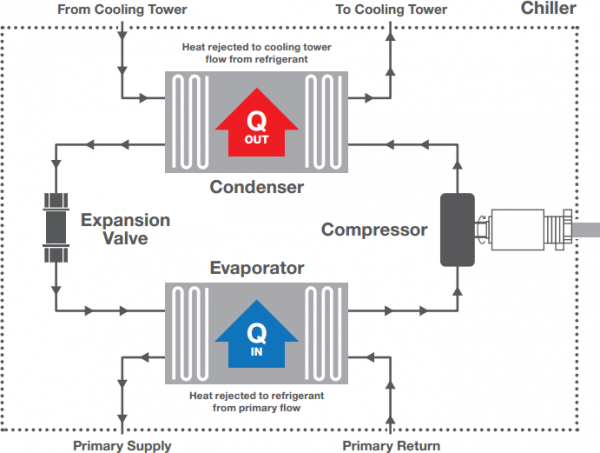
A Chiller is the main item of HVAC plant that provides the energy required to cool a building based on the peak heat gain. By using refrigeration gases, typically R410c or R134a, by compressing or expanding the gas (depending on the building demand) within the refrigeration cycle, energy is transferred through a heat exchanger into the primary water side system.
The required flow rate controlled via the control valve is then pumped around the system. For energy efficiency purposes it is essential that we aim to run chillers at the highest possible Coefficient of Performance (CoP), which is best achieved by having as high as possible delta T between the flow and return water temperatures. CoP is calculated as per the below.

The below diagram demostrates the refrigeration cycle and the main components of a chiller:

Recommended Installations
Pressure Independent Control Valve (PICV)
PICV
Stand Alone
PICV
- Easy to set up
- Straightforward commissioning
- No need for separate Commissioning Set and 2 Port Control Valve
- Available in sizes up to DN150
– Or –
Differential Pressure Control Valve (DPCV)
DPCV
Stand Alone
DPCV
- Range of controllable dPs available
- Available with Companion Valve
- Available in sizes up to DN150
- Requirement for control valves and commissioning set on individual units
Product Applications
Select from the product applications below to find out how dynamic balancing can improve installation on on-going operation.